I tried to think of, for about 2 minutes, some nice formal or perhaps funny way to introduce my self or start this post off but nothing came. That being said lets do this!
I believe to fully understand the Arduino, we must first look at its architecture and mimic it.
Most things we learn we learn by copying at first , do not take my word for it but it sounds about right.
In all my post if i am using any specific part i will give a link to where I got it from as well as part number and price, just because I love it when other people do that and find it helpful.
Parts From Jameco.com
28 Pin Socket : this is where you will insert your Atmega Chip, or you could permanently mount the pin but for
convinence purposes i sugest buying a socket that way you can remove the chip and adjust your code whenever you please. ( part number : 683171)
$0.25
This tactical momentary button will be our reset button, self explanatory there,but is it necessary? YES! right now i will not explain why but later i shall.
(part number: 162886) $0.35
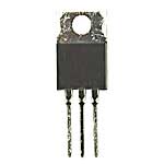
This is a very popular voltage regulator, basically when you power up your arduino with a 9 volt battery or any power source between 6 volts and 12volts this baby drops it down to 5v so you do not have your Arduino resembling a chimney. this is called a 7805 all the cool kids are using it. (part number: 51263)
$0.35
This is a 10 micro farad capacitor, for everything ive posted so far you only need one of each but you will need two of these, dont worry they only cost 6 cents . Basically this babies are to smooth the flow of voltage or current ? Because what if you have a power source that bounces between 6 volts and 7 volts, this baby will make it spit out a nice smooth flow. (part number : 29891) $0.06 need 2!
This is the same as above, a capacitor, except this is a ceramic type, and its value is 22 peco farads. these will go from our crystal to ground. whats a crystal?
(part number : 15405) $0.06 also need 2!!!!
This is a crystal, its that shiny silver thing on your Arduino, it runs at 16mhz and this is basically how arduino keeps time, how else is it going to know what delay(1000) is... (part number : 325139) $0.59
same as the other capacitors except its value is 0.1 micro farads (uf) , now this i did not use on my Arduino Clones but i found out today it is important. I will not show it on my build because i didnt use it but i will tell you where it goes. everything will function fine without it thought so no worries (part number : 544921) $0.14
you could also buy some female break away headers or just wire the pins you need
Now I ordered all these parts from Jameco.com in parts of 10 and some parts only 5 and still only spent 11 dollars :) how cool is that. Make 5 arduinos for 11 dollars. the only thing you still need which i will not give part numbers and price is because you can find this localy at Radioshack so paying shipping for it is not worth it. That includes your sodder, wires, at least 3 different colors to keep track of things. and prototyping/perf board
OK now here is one very useful image that I suggest you save .
This will help us figure out what goes connect where.
As far as getting the Atmega chips, thats the most expensive part which a bootloaded chip will run you about $4-$5. You can also get blank ones foe about 3 bucks and we can then dive into how to bootload those. But for this blog post let say you buy a pre bootloaded chip or just use the one on Your Arduino. Do a Google search for "atmega 328p-pu" and then click on shopping and take your pick.
I also assume you have resistors but if you dont , we will use one 10k ohm and one 220 ohm.
I know my intro says this is not mean to be a guide but sure does sound like one.
Now here are some pictures of what your finished product will look like. To the left I have an Arduino clone, which is being used by a Tv-Bgone clone , on a proto board. On the right i have another Arduino Clone but this time on a printed circuit board I made.
Now the difference is better seen when you look at the back.
You see how messy the one on the left looks compared to the right, its because on the perf board there are no "traces" so i had to use a wire to connect everything. But for now this is fine we just want to make a working Arduino no matter how pretty it looks.
Ok I will try my best to show this even though i am not in the process of building one right now and do not feel like it either.
so here we go!
first start by placing the socket in a convenient place, preferable with more available space on the left then the right since more components will go to the left of it. I will not post soldering picture because i assume you know you have to solder the piece on, and like i said i am not actually building one right now the pictures are just for reference. i will however suggest you just solder only the 4 corner pins It will make things easier to add the rest of the components. also the way you will be placing the Atmega chip is in a way that the upper left pin socket is where pin 1 of the chip will be.

Now if you go look at the diagram of the 328 (Atmega328p) you will see that the crystal goes connected to pins 9 and 10. It does not matter which lead goes to which pin , crystals are not diodes so there are no negative or positive ends. Place the crystal some where near where the 9 and 10 pins on the socket are so our connections do not have to stretch across the whole board. along with this step you will also connect one end of the 22pf capacitors to the crystal.. So the connection goes something like... pin 9 to one end of the crystal and on that same end of the crystal one end of the 22pf capacitor. Then do the same thing but on pin ten.Then the other end of the capacitors both will go to ground.Note: just because the 2 ends of the capacitors both go to ground do not connect them together, that is called a daisy chain and its not a good idea. when we add a power supply we will connect them individually to ground. , for now leave them like that.

Now Add the voltage regulator and a capacitor before and after it. The capacitor has to be connected properly, the negative side (short lead/ or side with the stripe) has to go to the ground of the regulator.
both capacitors negative side will go to the ground, however the one behind it will connect its positive side to the regulators input and the capacitor infront of the regulator will connect its positive to the output of the regulator. We will add Power over 5volts to the capacitor behind the regulator and it will smooth the voltage entering the regulator, then the regulator will drop the voltage to a steady 5volts, and then the capacitor in front of the regulator will further smooth the 5volts being outputted . from this capacitor is where we will wire the power to the chip and a power LED, which i forgot to mention on the parts list, sorry. I actually grabbed all the LEDs from our christmas lights.
Now add a button somewhere above the socket as well as an LED i wont show a picture because this is basic, do not solder them yet just put them on there for reference. the the 220 ohm resistor will be for the LED and the 10kohm resistor will be for the button. Lets talk about that Now.
Note: to make the following connections you can just use wire from one lead to the pins or if the component is close enough to reach just make sure nothing touches. What i did was just use wire and only strip the very tips so that when wires overlap they copper is not actually touching.
In order for the Arduino to reset you have to take Pin 1 and give it ground. but if we give it ground then it will always be resetting and we obviously do not want that so we have to connect that pin to a positive voltage with a very low current, hence the 10k resistor , so you will have a 10k resistor to pin 1 , then the other end of the resistor to positive 5v coming out of the capacitor INFRONT of the regulator.
Also to pin 1 we will connect the button because we also need to be able to reset at our will. So connect one pin of the button to ground and another pin to pin 1 on the 328,
when i say 328 i actualy mean the socket but this is where the chip will go so its the same thing. And when i say ground it also means ground of the capacitor INFRONT of the regulator. Also remember with those buttons with 4 leads , pin 1 is always connected to pin 2 and pin 3 is always connected to pin 4, so you have to connect pin 1 to pin 3 or pin 2 to pin 4 , the only time those 2 pairs are connected is when you press the button and thats when we will send the ground signal to pin 1 of the chip to reset it. you can play around with an led to find out which pins are which.
Also looking at the Above Picture pin 7 and 8 are Power to the chip and ground respectively. So you connect 5 volts coming out of the capacitor INFRONT of the regulator to the vcc pin 7 and Pin 8 gets grounded with the ground / negative of that same capacitor. when i say power and ground from now on i am referring to the capacitor INFRONT of the regulator i just dont want to keep repeating my self.
If you look once again at the picture pins 21 and 20 also go to 5v and pin 22 goes to ground.
Also remember the end of the capacitors leaving the crystal go to ground.
As far as the power led goes just connect the anode to positive 5v and the 220 ohm to the cathode and the other end of the resistor to ground.
Okay one usefull tip so you dont have an ugly mess of wires is to grab some wire and strip it completely and connect it to ground and run that wire down one side of the board, so that when you have to connect something to ground you just connect it to that wire , instead of 50 wires all trying to connect to the capacitor. same goes for the positive side 5volts side. I didnt do that so i have no picture to show.
Now to make this usefull you can add female headers so your clone resembles the functionality of an Arduino.
wire the headers to the corresponding pins , in the picture it tells you which Atmega pin does what in the Arduino, for example if i wanted to use my analog pins i could add some headers to the top right near the socket and wire each of those to each pin on the socket and i can use those analog pins. You can add headers for all the pins or just what you need for a certain project that is up to you.

To add power to this baby add 2 female headers, like the ones shown above, behind the the capacitor that is BEHIND the regulator wire one header to the positive and one to the negative and this where your power supply will be plugged in. to get a steady 5v out of the regulator you should supply over 5volts . i am too lazy to research the ratings on the 7805 right now to tell you the max volt it can handle but im sure you can find that out. Also do not forget to add female headers connected to , because most sensors and other things need ground so you have somewhere to plug their grounds. the arduino only has about 3 so if you need to ground something else you need to start using your digital pins and setting them low , but if you add ground pins then it helps save those digital pins for other things.
And if you want a "5v" pin just like the arduino then add a female header and wire it to 5v from the front capacitor and if you want a "Vin" pin like the Arduino add a female header and wire it to the positive side of the capacitor BEHIND the regulator.
Now all you have to do is add the 328 and connect your sensors etc... remember the atmega chips has to be oriented right, on the top of the chip there is a little notch shaped like a "U" that is the top and that goes to the side where the button is.
and that is about it, if I have forgotten something please let me know since i am not building one as i type i could of forgotten something. Also let me know if you have any questions.
My next post will be on further developing this and ill dive into the boot loading process if you have blank chips. You can also build this on a breadBoard. the tutorial is found
Here